


Description
HOW IT WORKS
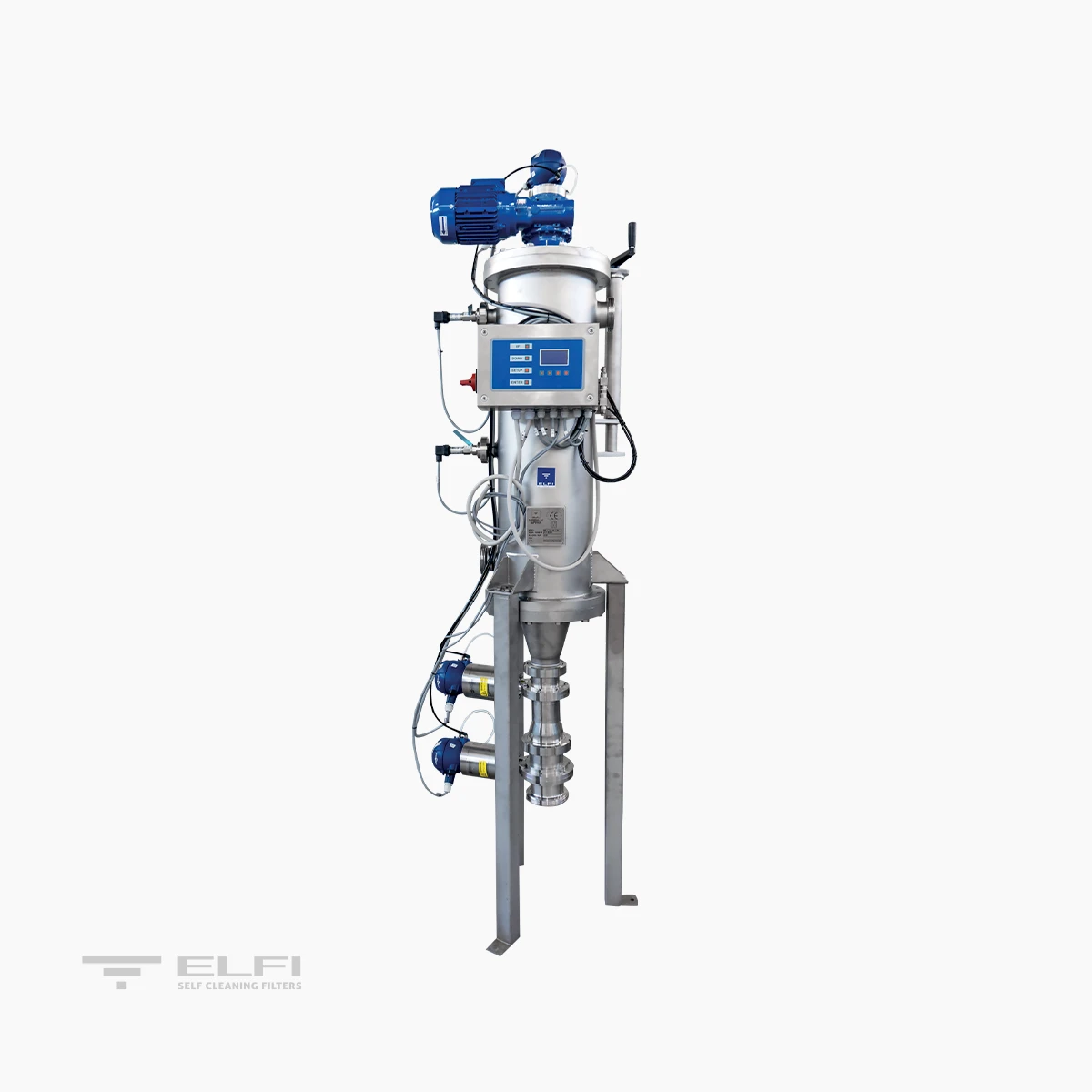
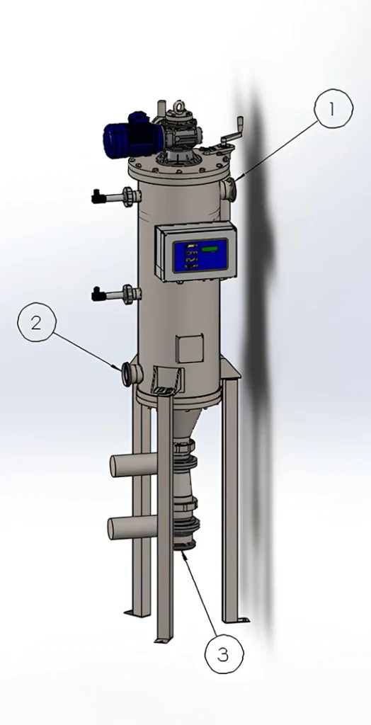
The fluid enters the filter through the inlet (1) and flows from the inside to the outside of the filter cylinder. All non-deformable suspended solids larger than the filtration grade are retained on the filter surface. The treated fluid exits through the outlet (2).
REGENERATION SOLID/LIQUID DISCHARGE
The fluid enters the filter through the inlet (1) and flows from the inside to the outside of the filter cylinder. All non-deformable suspended solids larger than the filtration grade are retained on the filter surface.
The treated fluid exits through the outlet (2). How it works The cleaning phase is carried out using an innovative patented solution. The scraping blades, positioned tangentially inside the filter element, gently remove the solids deposited on it. The impurities are directed toward the concentration and discharge zone (3).
Impurity discharge is performed via two valves to compact the solids as much as possible. The washing cycle is time-controlled or pressure-differential controlled and is adjusted according to the amount of solids and the flow rate to be treated. During the cleaning phase the flow is not interrupted. The new solution adopted for the scraping blades significantly reduces wear on both the blades and the filter element, consequently minimizing potential contamination of the filtered fluid.
CONTROL
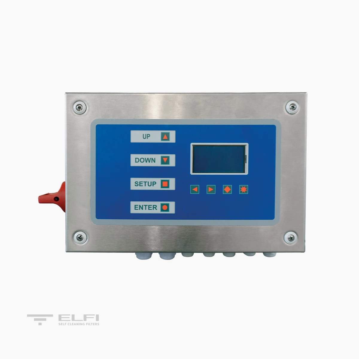
An electrical control panel manages the regeneration and washing phases. The cleaning cycle can be triggered by pressure differential via installed transmitters or by timer. The interval between openings and the discharge valve opening time can be adjusted. The panel is equipped with a push-button interface for manual motor operation. The discharge valves can also be opened manually via the solenoid valve actuator. An alarm signal indicates the absence of motor rotation during the washing phase. The software also controls the CIP washing phases at the end of the production cycle.
DIMENSIONS AND TECHNICAL DATA
| MODEL | SPIROCLEAN 20 | SPIROCLEAN 30 | SPIROCLEAN 45 | SPIROCLEAN 60 |
|---|---|---|---|---|
| Filtering area (cm²) | 2000 | 3000 | 4500 | 6000 |
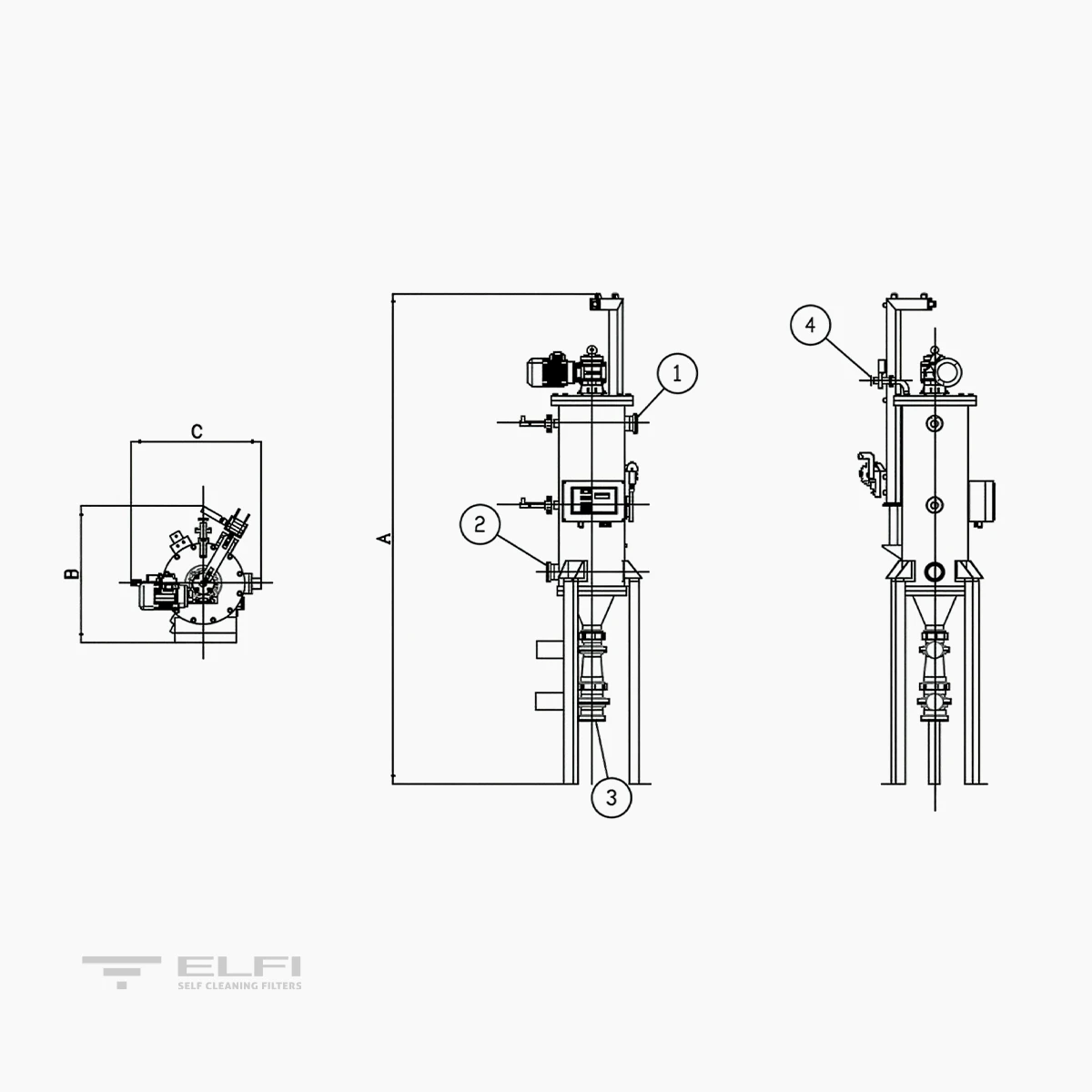
| In/Out (1) (2) | DN 50 F | DN 60 F | DN 65 F | DN 65 F |
| Discharge/Drain (3) | DN 80 F | DN 100 F | DN 100 F | DN 100 F |
| Air vent (4) | DN 25 F | DN 25 F | DN 25 F | DN 25 F |
| Min-max pressure – Bar | 0,5-10 | 0,5-10 | 0,5-10 | 0,5-10 |
| Max Temperature – °C | 90 | 90 | 90 | 90 |
| Max flow rate – m³/h | 45 | 45 | 45 | 65 |
| Power supply – Volt | 400 50/60 Hz | 400 50/60 Hz | 400 50/60 Hz | 400 50/60 Hz |
| Power required – Watt | 180 | 370 | 370 | 550 |
| Solenoid valve – Volt / Watt | 24 AC / 6 | 24 AC / 6 | 24 AC / 6 | 24 AC / 6 |
| Pneumatic supply – Bar | 2 – 8 | 2 – 8 | 2 – 8 | 2 – 8 |
| Construction certificates | CE | CE | CE | CE |
| Pressure vessel code | EN 13445 | EN 13445 | EN 13445 | EN 13445 |
| Volume – Liters | 28 | 48 | 72 | 95 |
| Davit | Included | Included | Included | Included |
| Foot | Included | Included | Included | Included |
| A (mm) | 1851 | 1895 | 2120 | 2150 |
| B (mm) | 516 | 586 | 586 | 611 |
| C (mm) | 562 | 618 | 618 | 664 |
| D (mm) Cartridge extraction | 700 | 700 | 950 | 950 |
| WEIGHT when empty Kg | 82 | 112 | 137 | 232 |
| WEIGHT in operation Kg | 108 | 154 | 195 | 293 |
Technical data are indicative and subject to change without notice.
• Maximum flow rate: 100 micron, 1 CSP, ΔP 0.2 bar.